Introduction
First of all, I don’t know how to play any instrument, and I have no formal musical knowledge 😄
I work as an IT Systems Administrator, and I’m good with electronics. I don’t have much woodworking experience, but I can handle basic tasks. My grandfather was a skilled woodworker - when I was a kid, I really enjoyed watching and helping him. I’ve inherited some of his tools, which inspired me to take on this project.
I decided to build a MIDI organ pedalboard for my son. He plays piano, organ, and harpsichord, and wanted a pedalboard so he could practice organ at home. He had been searching online for quite some time, but all the finished products seemed a bit overpriced. Then he came across an Italian organ builder who sells pedalboards in kit form: https://www.pedamidikit.org/. There, you can buy pedalboards as unassembled and unpainted kits at a very reasonable price.
If you’re thinking about building a pedalboard yourself, think twice - it might be a bit cheaper, but it will definitely require a lot of time and patience. This is the model my son was interested in:
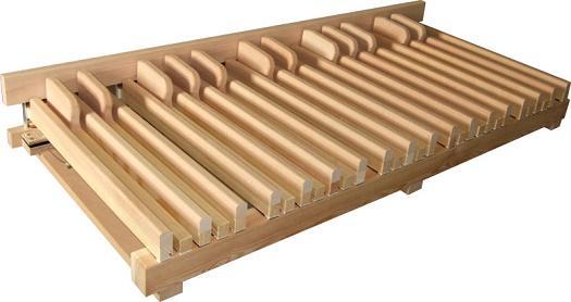
It’s the 30-note straight “Naked” model from PedaMidiKit: https://www.pedamidikit.org/pmkstnk30.html/
Why straight? In this part of the world, many pedalboards are straight, including the organ at the music school where my son practiced, which was made by Johannus:
I started searching online and found a lot of useful information. Some people suggested buying used pedals from old organs and adding MIDI to them. That’s probably the easiest way, but I couldn’t find a 30-note straight pedalboard. Most of the available ones were in the USA - overpriced and with expensive shipping.
Then I found tutorials and drawings from other DIY projects. So… how hard can it be? The decision was made - I would try to build it myself.
Here is a list of very usefull links:
- The Organ Forum: https://organforum.com
- Russian MIDI Pedalboard builder: https://midipedalboard.narod.ru/EN/manufact.htm
- Norwegian MIDI Pedalboard builder: https://fagerjord.org/pipe-organ/524/2/
- Youtube Video from Jacek Jarzina: https://www.youtube.com/watch?v=skIXdKvqTZk
- MIDI hardware Electronic Modules: https://www.midi-hardware.com/
Roman from MIDI Hardware is the best! We exchanged a few emails, and his advice was very helpful. Even though there was a warning about longer waiting times on his webshop due to a busy period, he still managed to ship everything very quickly. (More about the electronic parts later.)
Project Launched!
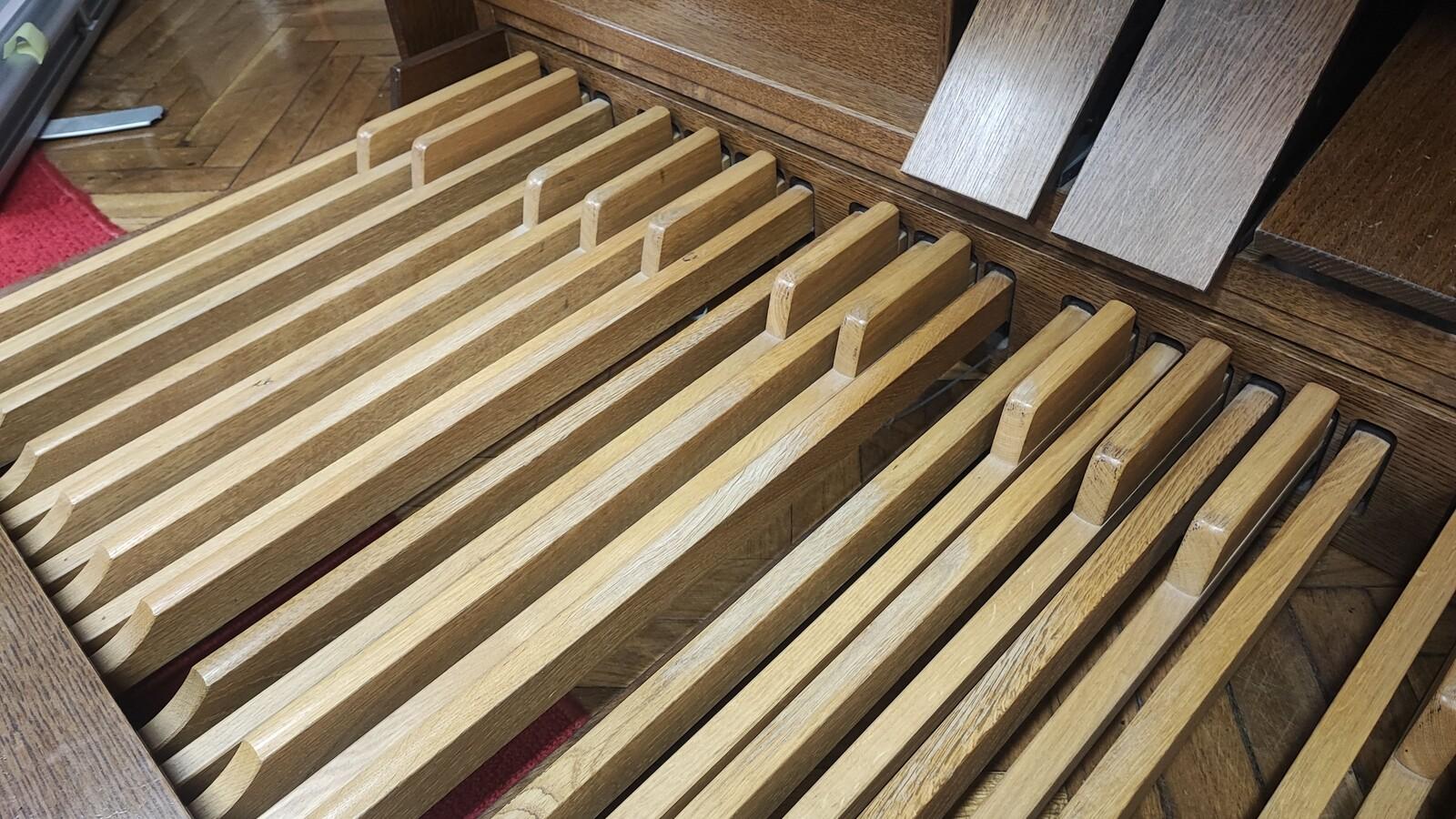
So we went to the music school to take some measurements. The dimensions were pretty standard: 33 mm pitch, 21 mm note width, and the length of the keys was about 670 mm. There were torsion springs at the back of the (visible) keys. Key travel was about 15 mm at the far end, with the notes activating at about half of that. The sharps protruded about 30 mm above the naturals.
There was also a variation in the length of the sharps - the longest was about 210 mm, and the shortest around 100 mm. I liked the material (oak), but the keys were varnished and looked like they would need sanding and repainting (more on that later).
Material:
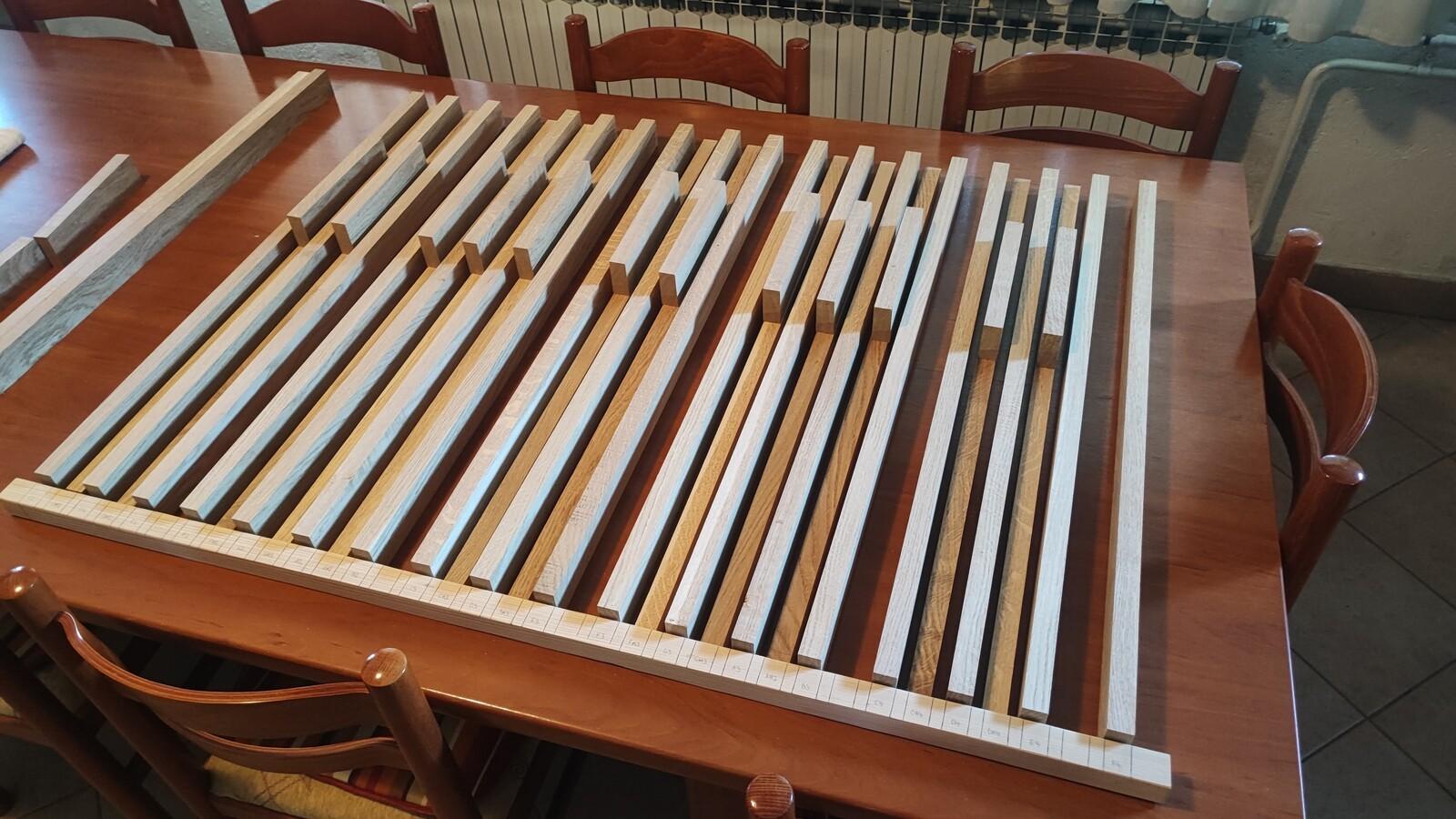
Some of the drawings I found online suggested a key width of 22 mm, so I ordered oak wood elements from a local woodworking shop with the following specifications:
- 22 × 44 × 850 mm - 18 pcs - for the natural keys
- 22 × 22 × 850 mm - 12 pcs - lower part of sharps (or “sharp carriers”)
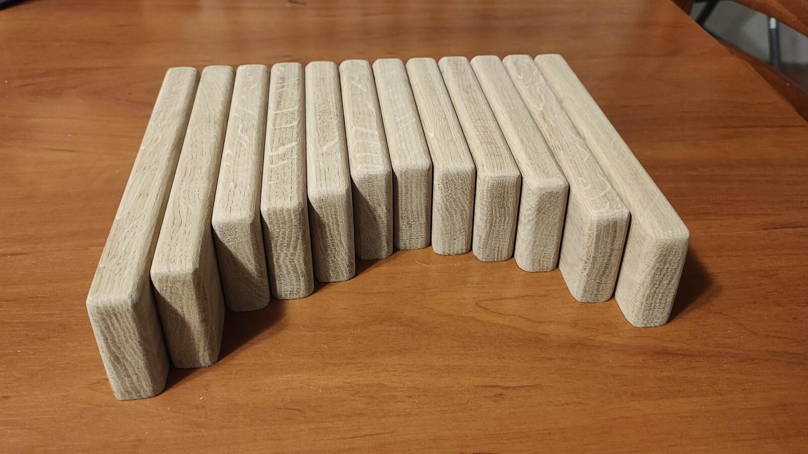
- 22 × 52 × 210 mm - 12 pcs - upper part od sharps (actual sharp keys)
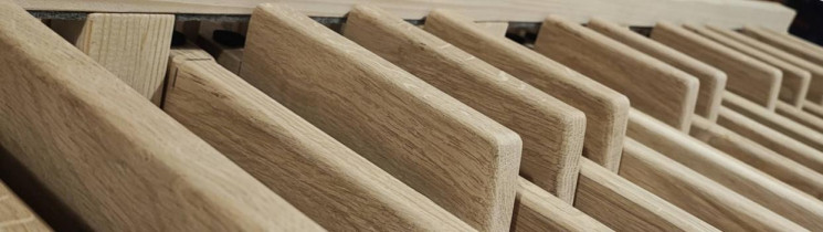
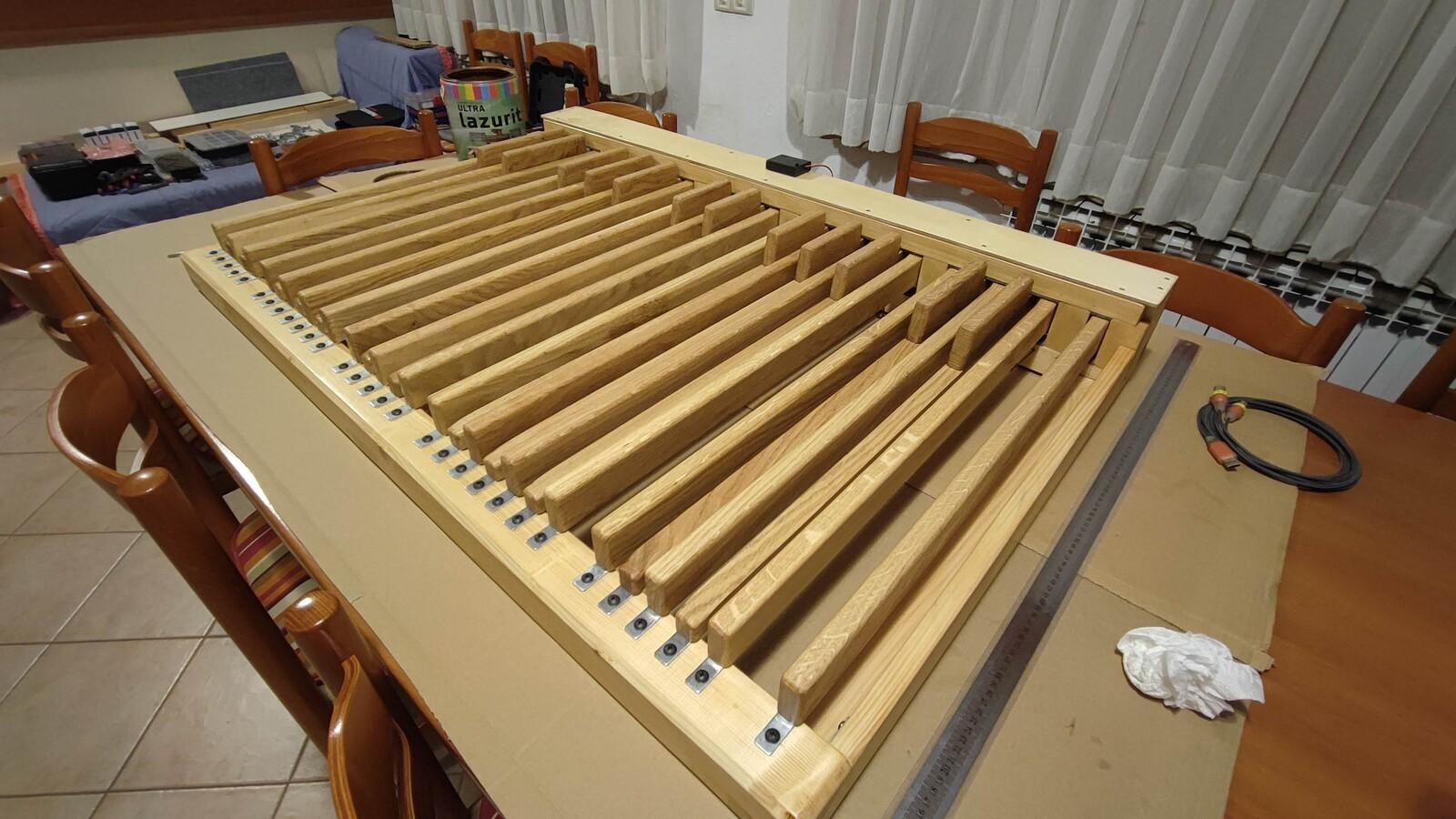
In fact, I ordered a few extra pieces, just in case something went wrong during cutting. I also ordered them a bit longer than needed, because at that point I wasn’t sure exactly how or where I’d mount the MIDI electronics for the keys. The wood arrived two days later - absolutely beautiful, straight, and cut exactly to size! I only have hand tools and no machines like a surface planer, so I never could’ve made them this precisely on my own. Here they are:
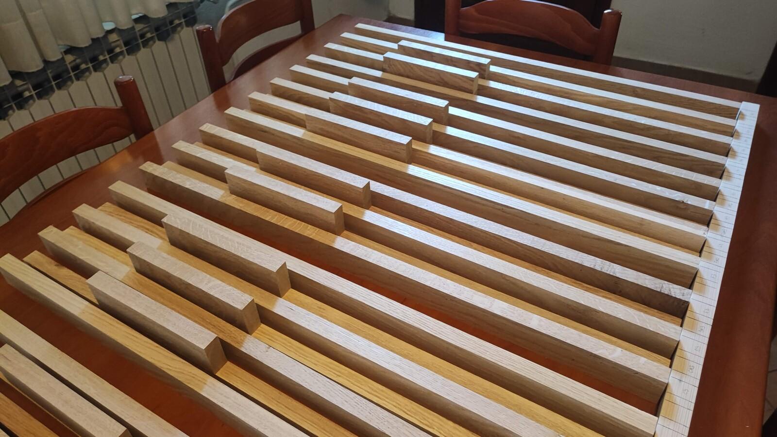
This marks the official start of the project: 19th of June, 2025.
Tools:
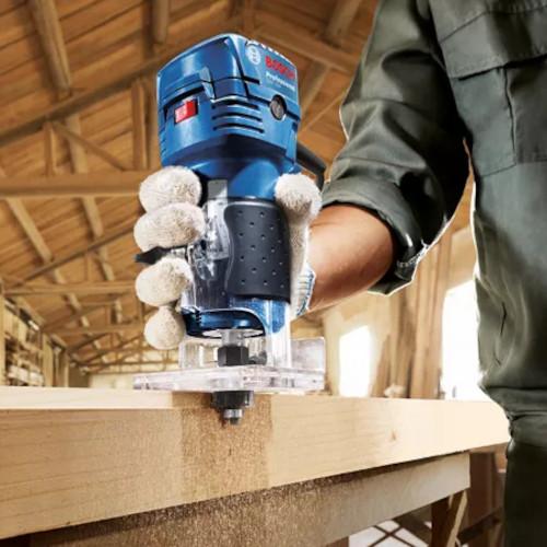
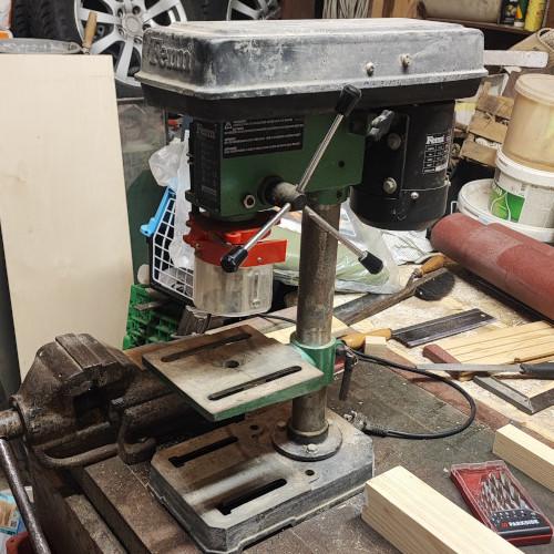
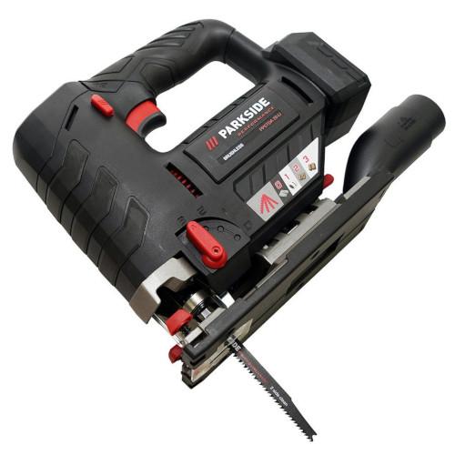
Besides standard tools (like a cordless drill, jigsaw, random orbit sander, screwdrivers, and a hand saw), I needed two additional tools: a palm router (mostly for rounding edges) and a bench drill (because this project involves drilling a lot of holes). I bought a Bosch GKF 550 Professional Palm Router along with a set of bits for it. Then I remembered I had an old FERM bench drill - about 40 years old! I cleaned it up and gave it a try. It wasn’t perfect (it needs a new chuck), but it was good enough for this project. I also used a Parkside cordless jigsaw, and I was pleasantly surprised by how well it performed.
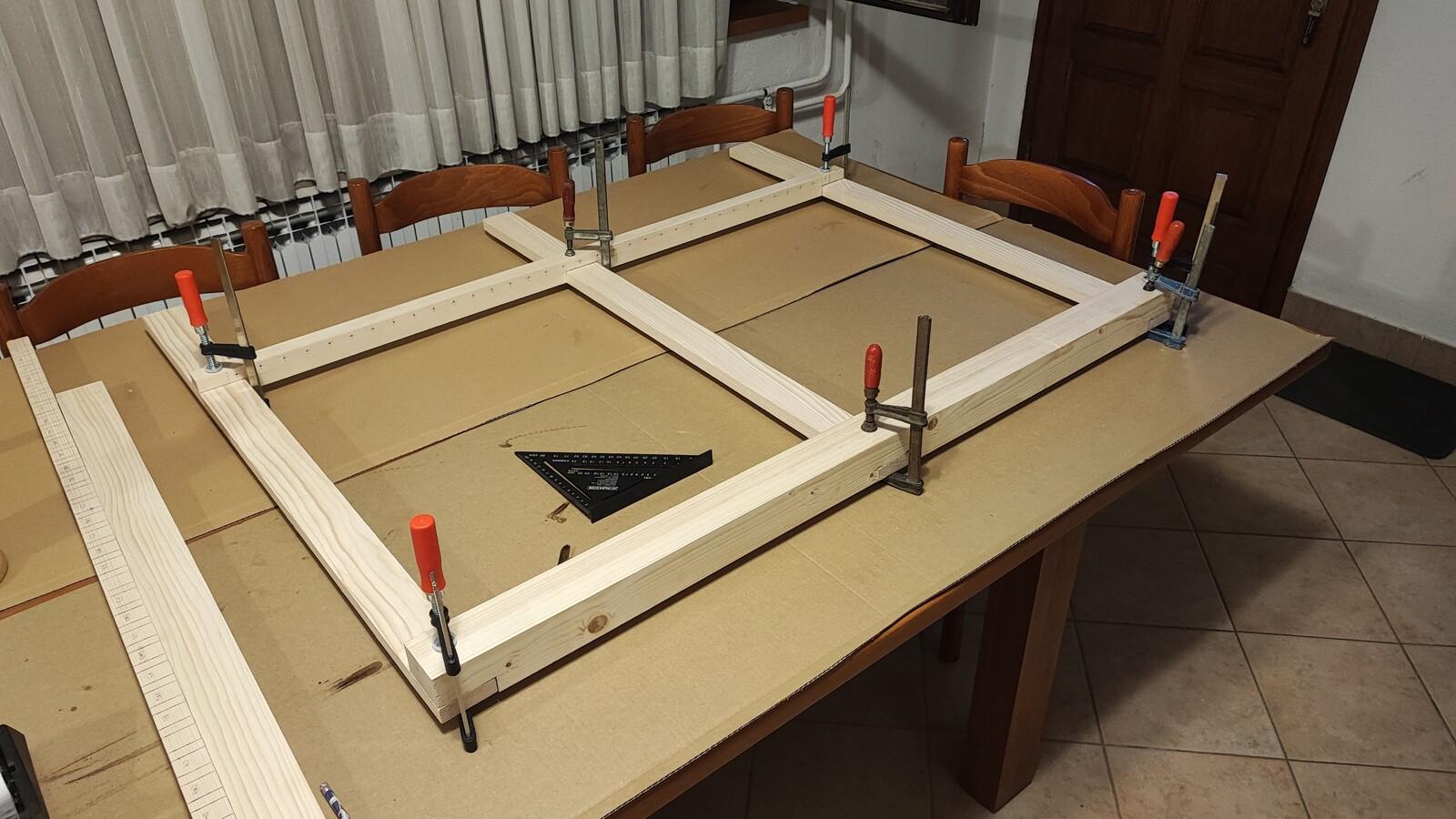
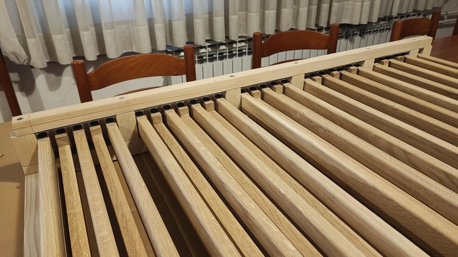
The Frame
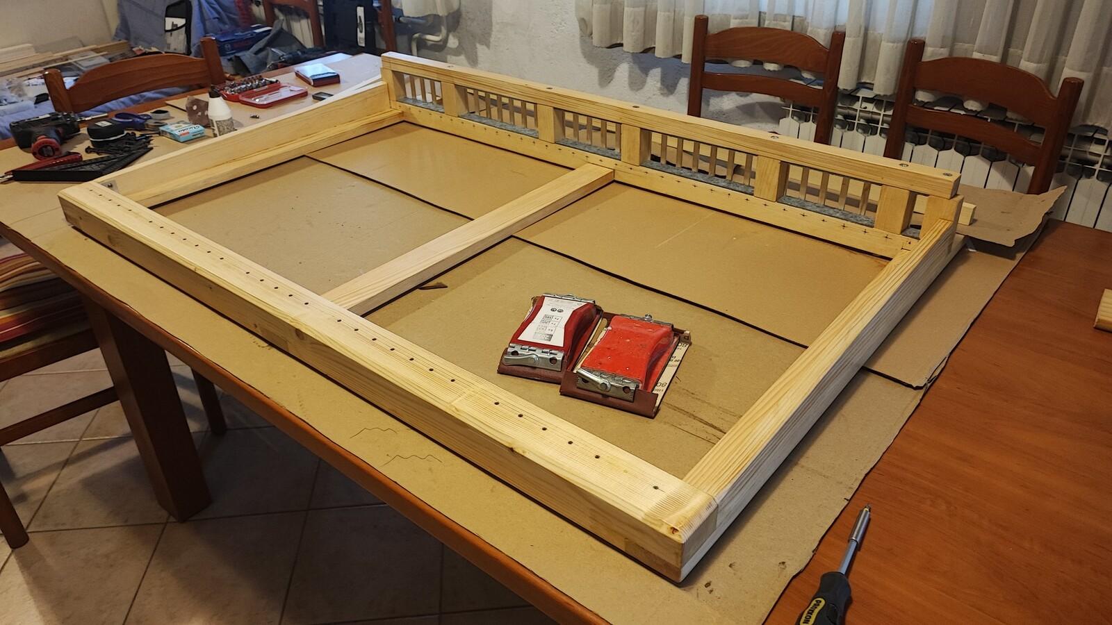
The frame is built from pine wood. The front element measures 60 × 60 × 1224 mm. The rear bottom element is 30 × 40 mm, and the rear top is 30 × 30 mm. The side and middle boards are 20 × 60 mm. These boards were left longer than actually needed, since I didn’t have the electronic parts at that time. The distance from the front to the rear element is 660 mm.
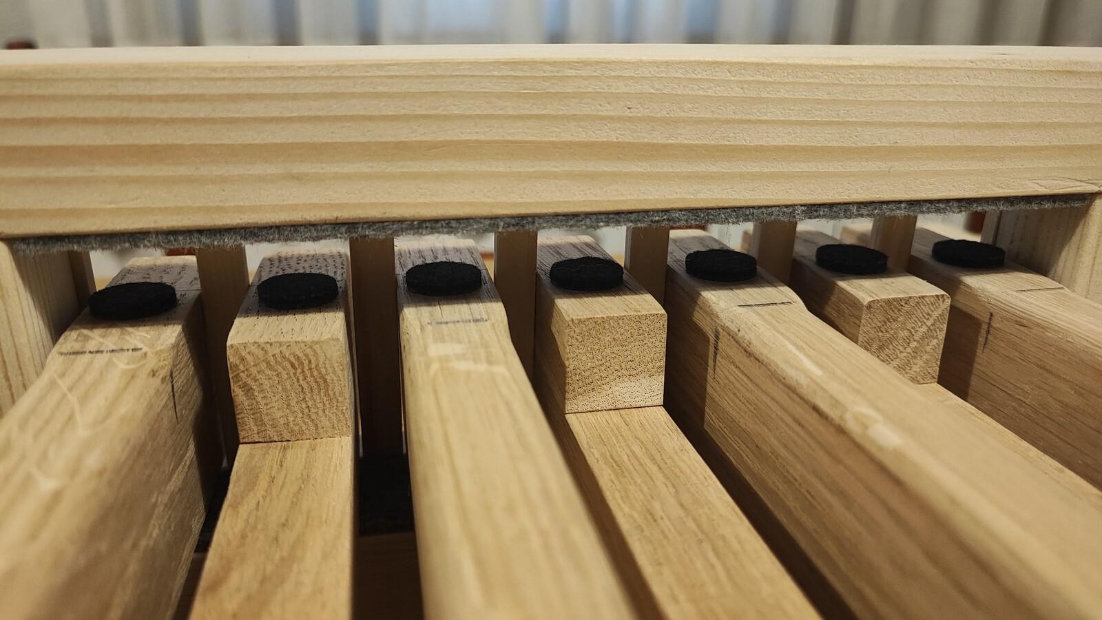
Vertical pieces connecting the top and bottom rear elements are 40 × 30 × 68 mm. That allows key movement of about 16 mm (44 mm is the height of the keys, 16 mm key travel, and 4 mm for felt on each side). The top and bottom rear elements are connected using 130 mm long screws. Holes in the vertical pieces are drilled to 10 mm diameter to allow precise placement.
I cut stripes from felt and glued them to top and bottom rear elements.
Later, I added side reinforcement using two pieces glued and screwed to the side boards. This was done to prevent the frame from bending. The whole frame sits on the floor on six silicone legs.
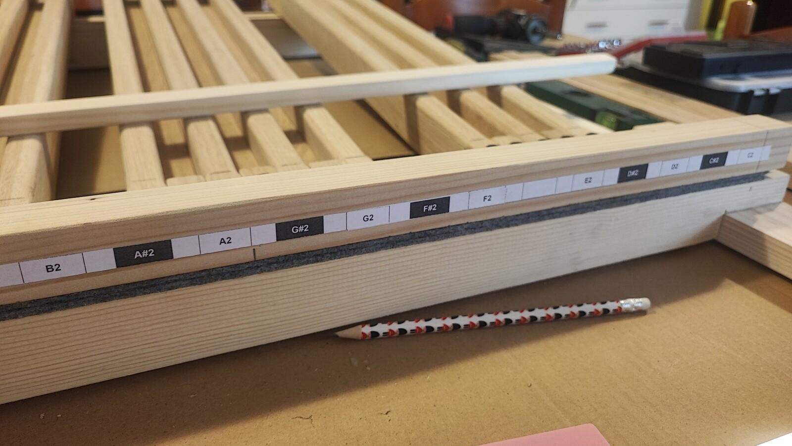
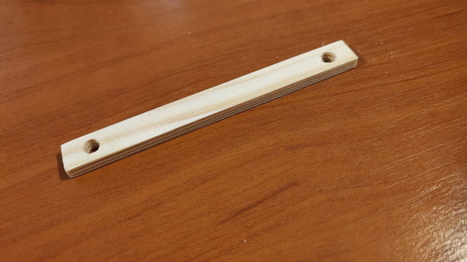
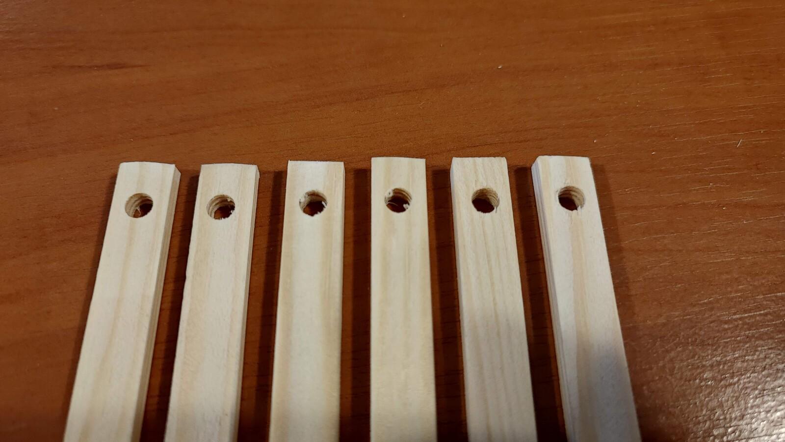
Spacers between the keys are made from pine wood, measuring 5 × 10 mm. I made a stencil for drilling 5 mm holes at both ends. I planned to add cloth around these spacer elements to ensure silent and smooth movement of the keys.
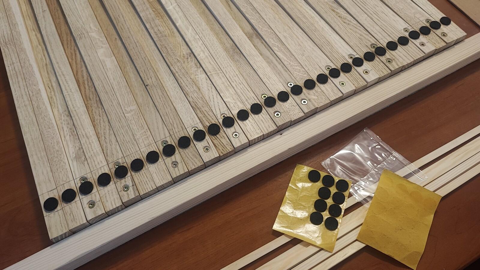
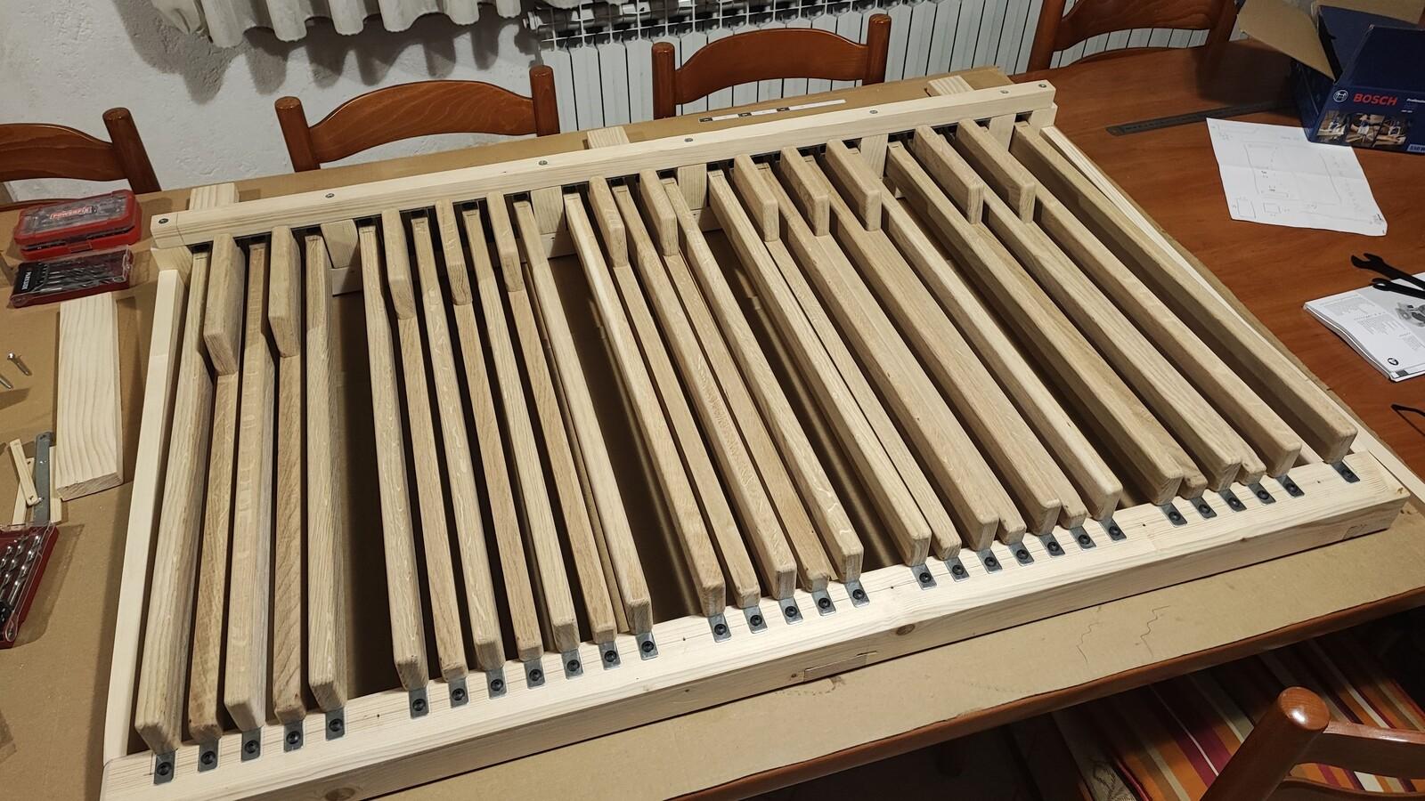
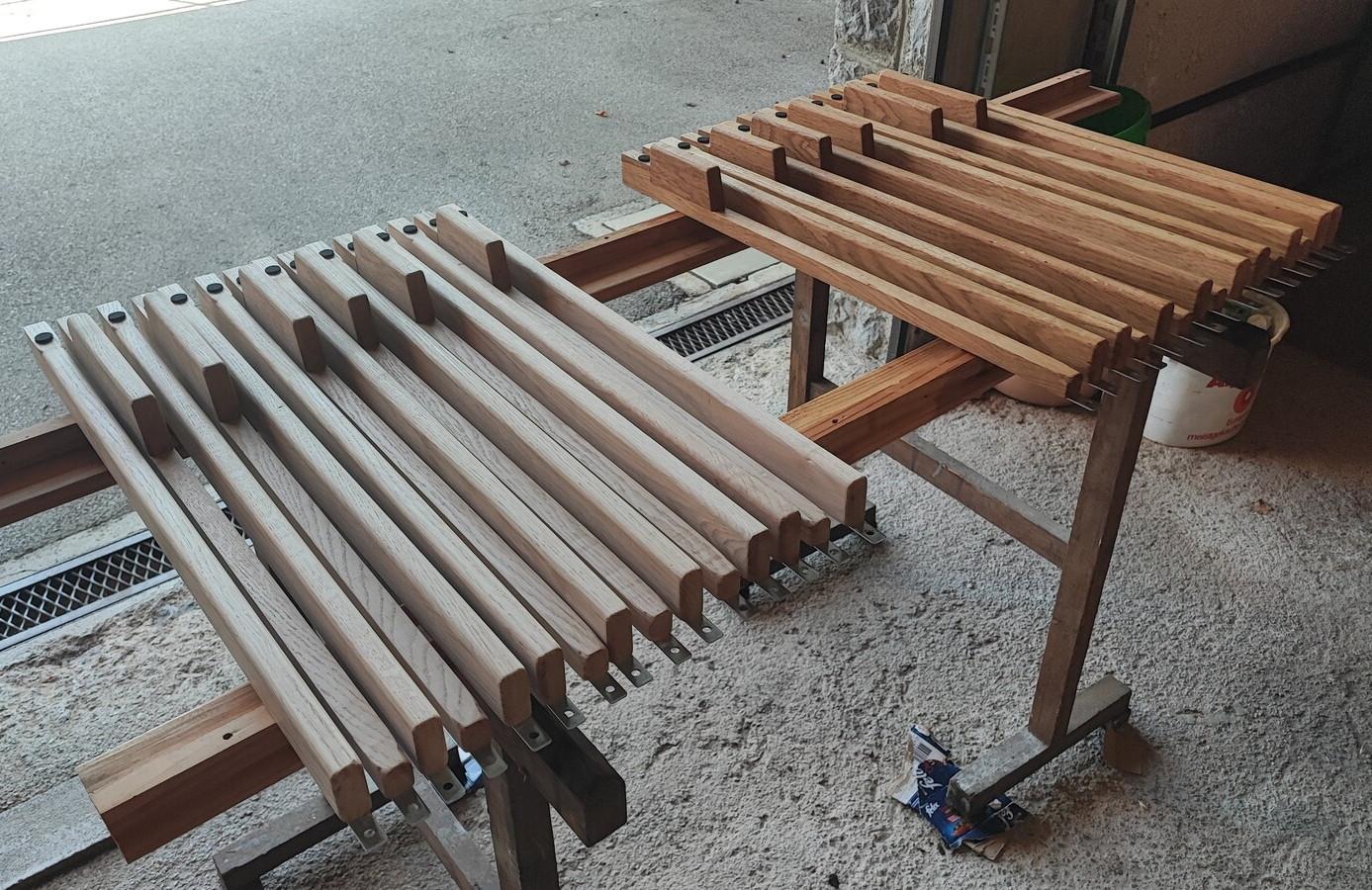
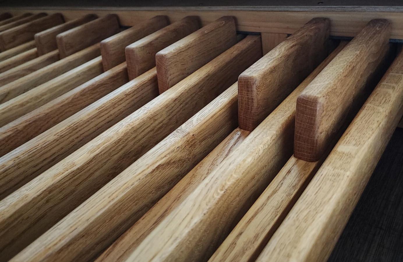
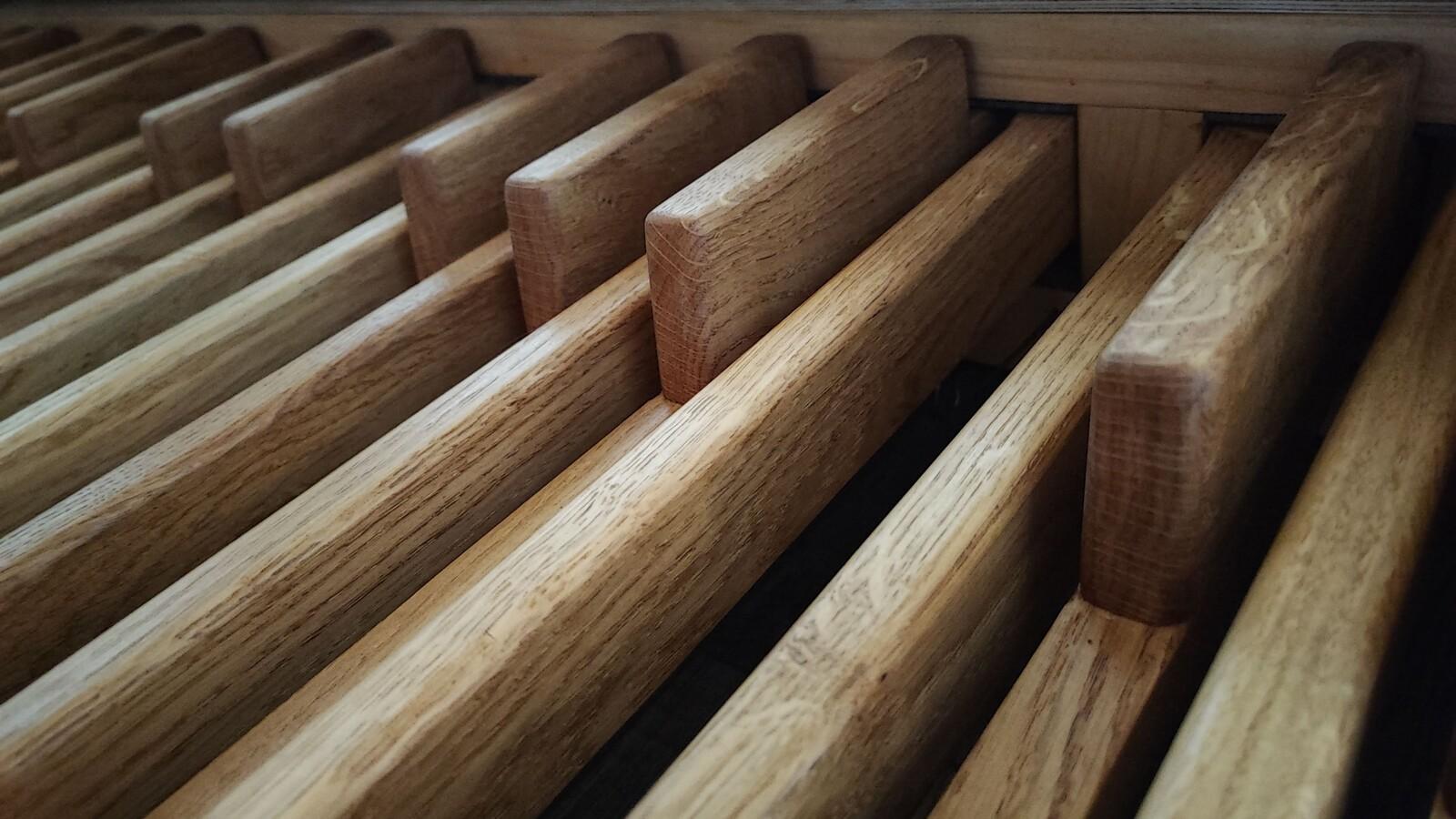
The keys
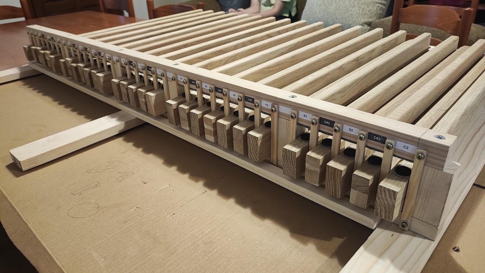
The wooden elements for the keys were originally 850 mm long, but I shortened them to 720 mm. I used the leftover 22 × 22 mm pieces to make the ends of the keys all the same height (44 mm). I used glue and screws to ensure they were perfectly aligned. Then I added self-adhesive felt pieces to the top and bottom of the keys.
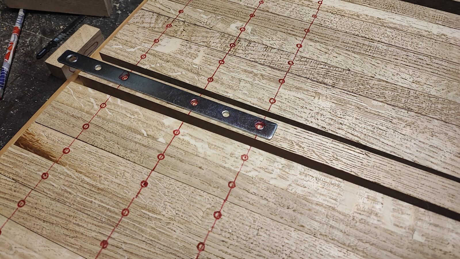
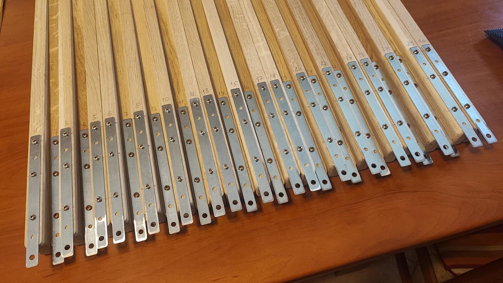
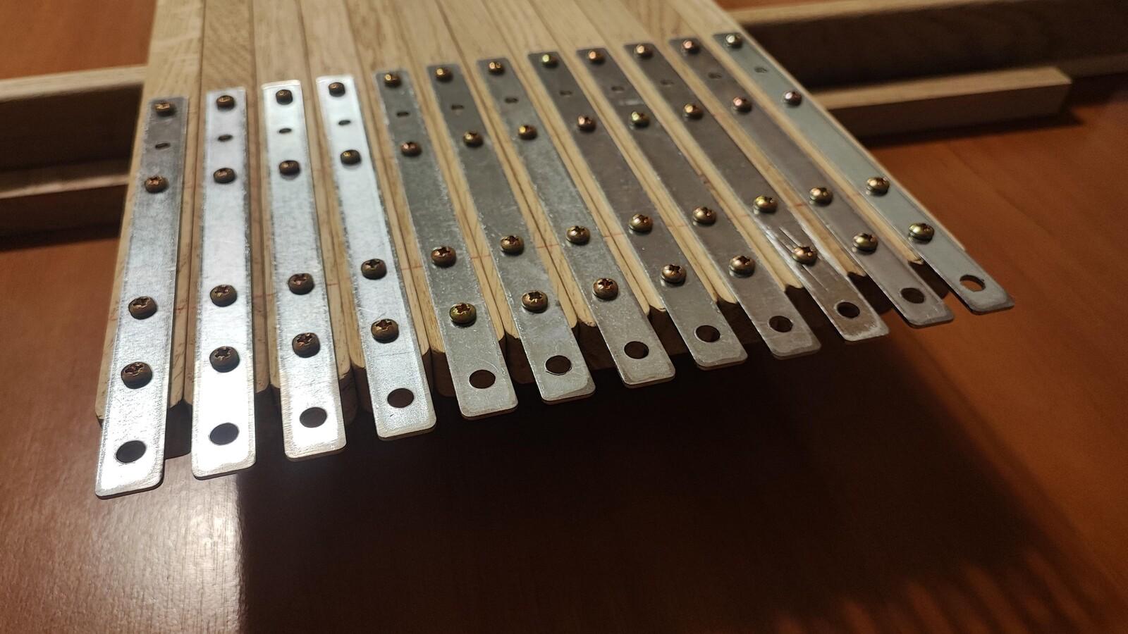
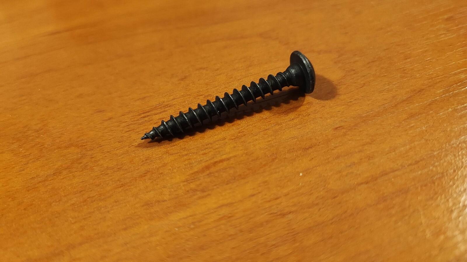
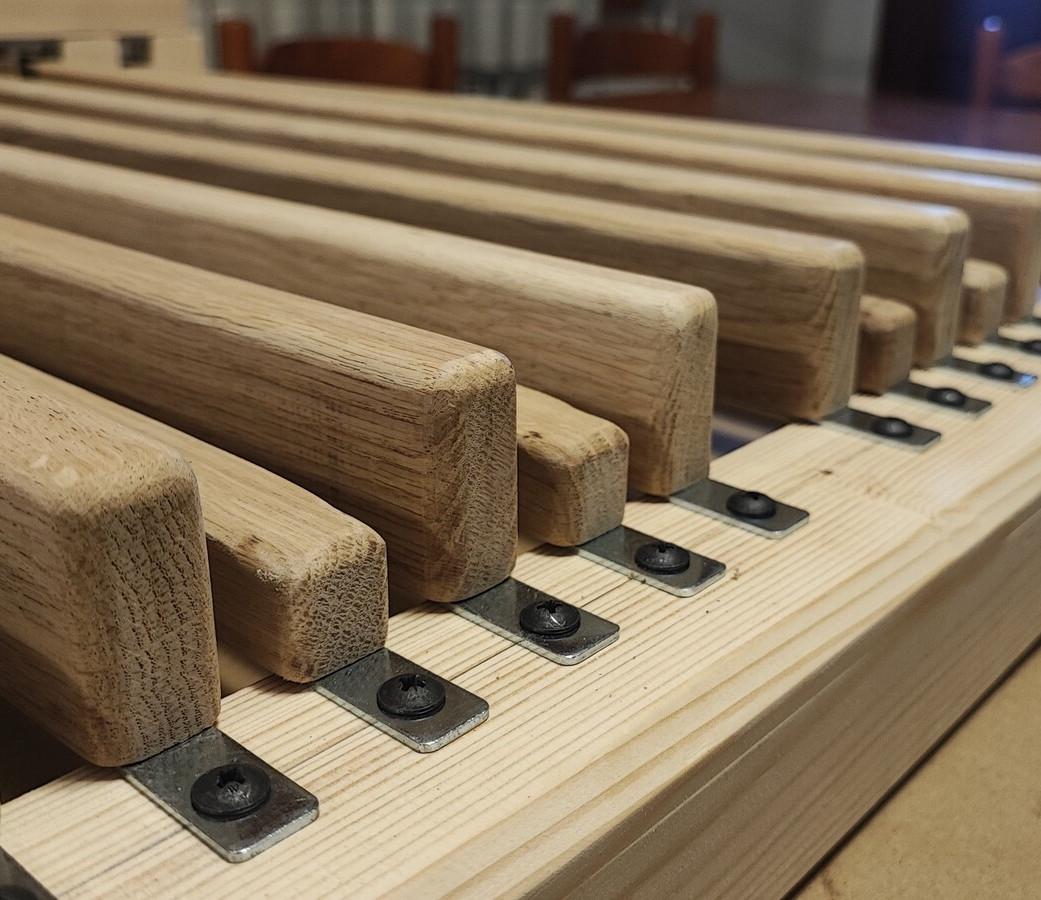
For hinges, I bought galvanized steel bars with six holes in each. My initial plan was to use four screws: one large screw (5 × 40 mm, with a wider head) to secure the key to the front of the frame, and three smaller screws to attach the metal bar to the key.
I intentionally left the first screw hole on the key empty, thinking it would give the metal more “bending space.” That turned out to be a mistake - it also introduced a lot of side wobble (torsion) to the key. So I added the fourth screw to each key later. That fourth screw is important, keys are much sturdier and doesn’t move sideways!
I also had to widen the first hole slightly to allow for adjusting the keys during installation.
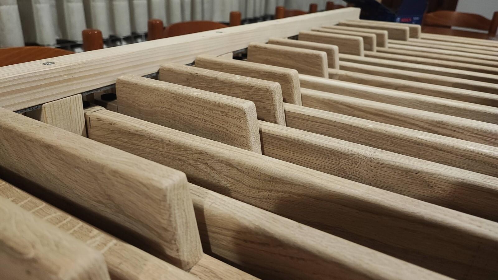
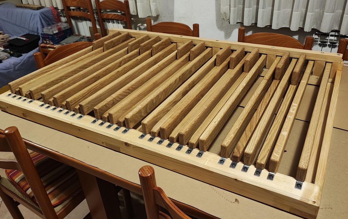
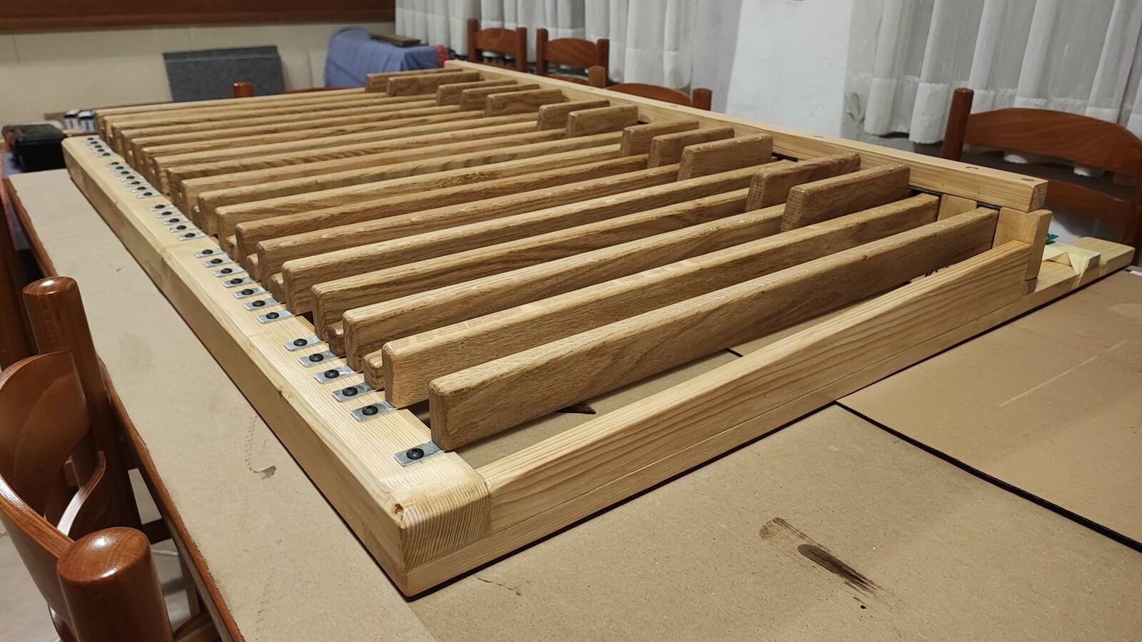
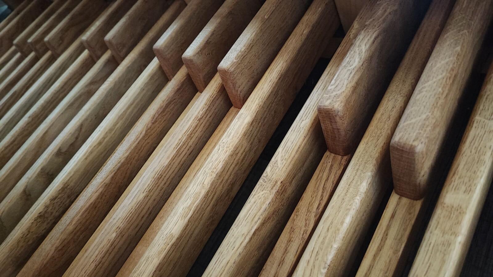
Sharps:
The length of the sharps was determined by drawing part of a circle using a piece of string 1900 mm long. The sharps are slightly slanted at the front, and their corners are rounded - just like on the natural keys, with 6 mm radius corner bit for palm router.
The sharps are connected to their carriers using longer screws (4 × 50 mm). I didn’t use glue (for now), because my son thought we might need to make some adjustments later. So far, they seem very sturdy with just the screws.
Finishing and Painting
I sanded all the elements with my random orbital sander - first using 120-grit, then 240-grit sandpaper.
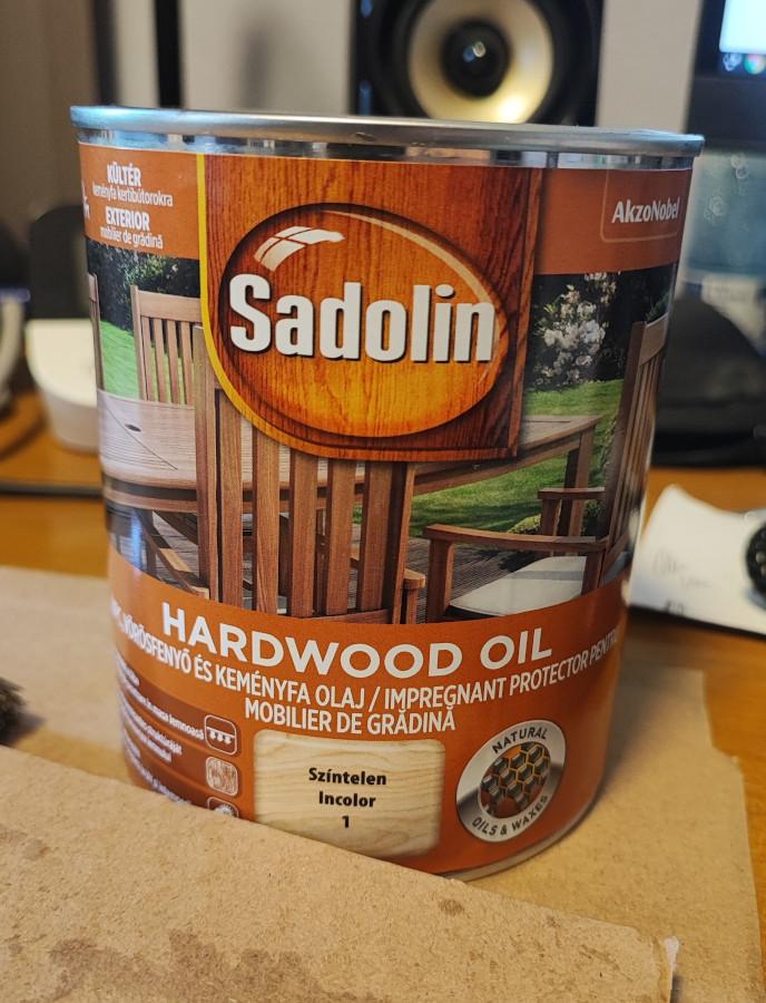
I decided not to use varnish for the keys. It’s a more complex process, and any repainting later (due to wear and tear) would require disassembling the keys. Instead, I chose to use clear hardwood oil. For the pine wood parts, I used regular clear wood paint.
This was my first time using hardwood oil, and I’m very pleased with the results. The process is simple: I applied it with a regular brush, then wiped off the excess oil using a piece of cotton cloth. I repeated the process 24 hours later. In my opinion, oil gives the wood a more natural and pleasant look.
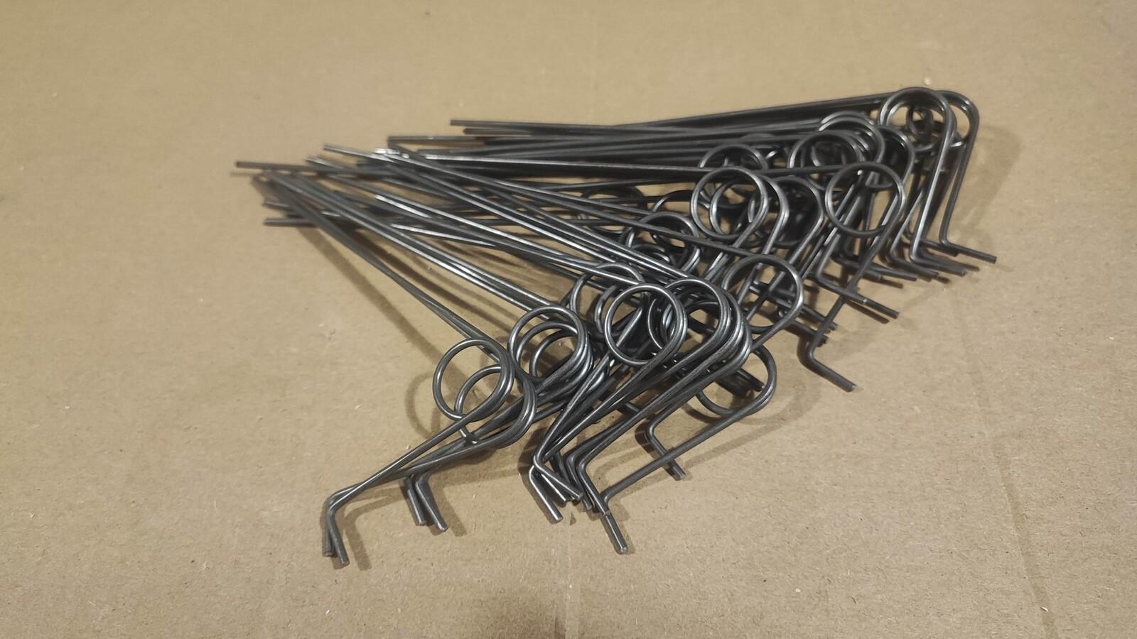
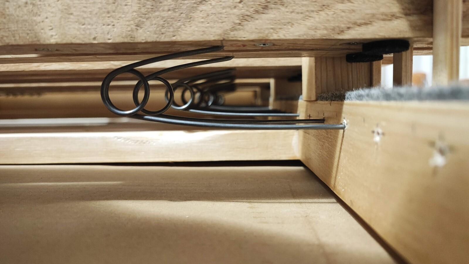
Springs
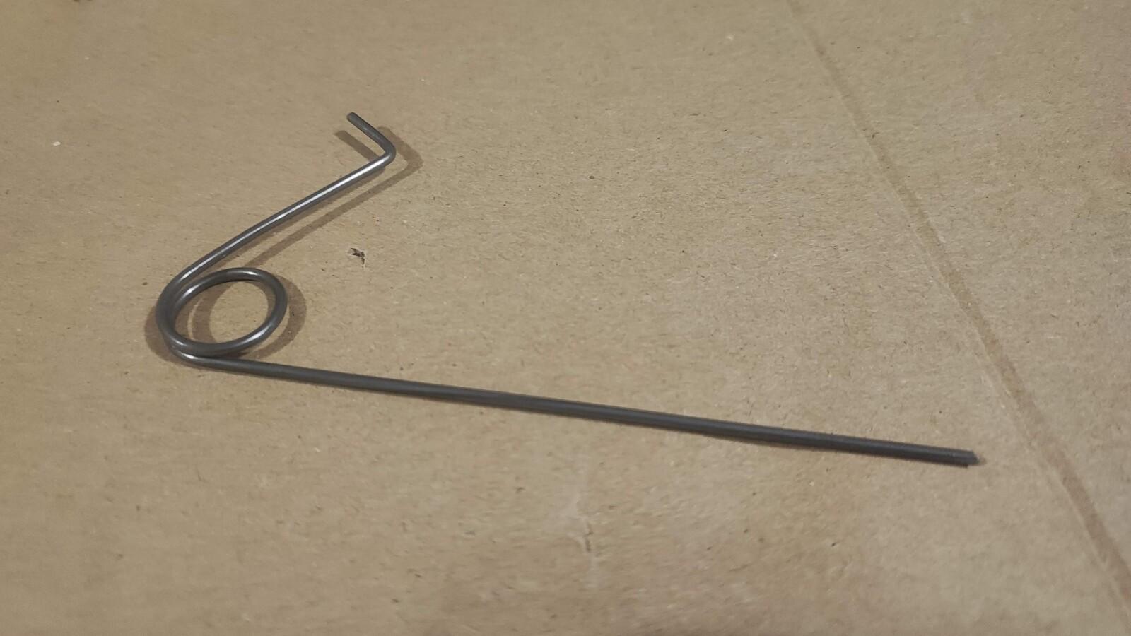
I made the springs from 2 mm piano wire, which I bought from Conrad Electronic. They sell it in 1000 mm lengths, so I decided to use 250 mm per spring.
First, I made a prototype using copper wire to test the shape and length. I chose a smaller spring diameter (14 mm) because I didn’t have much space beneath the keys, and my wire was thinner than what I saw in other DIY projects online.
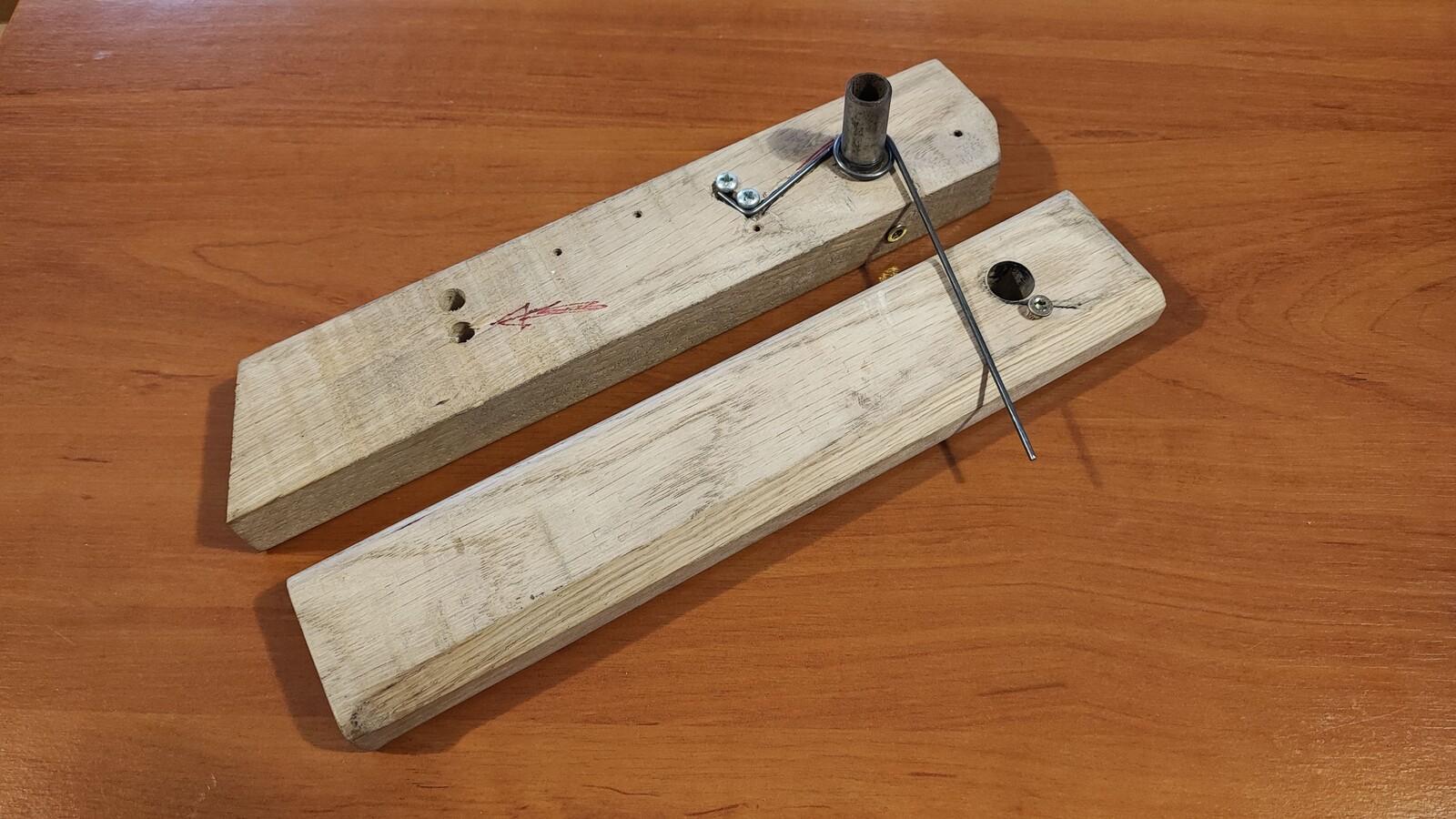
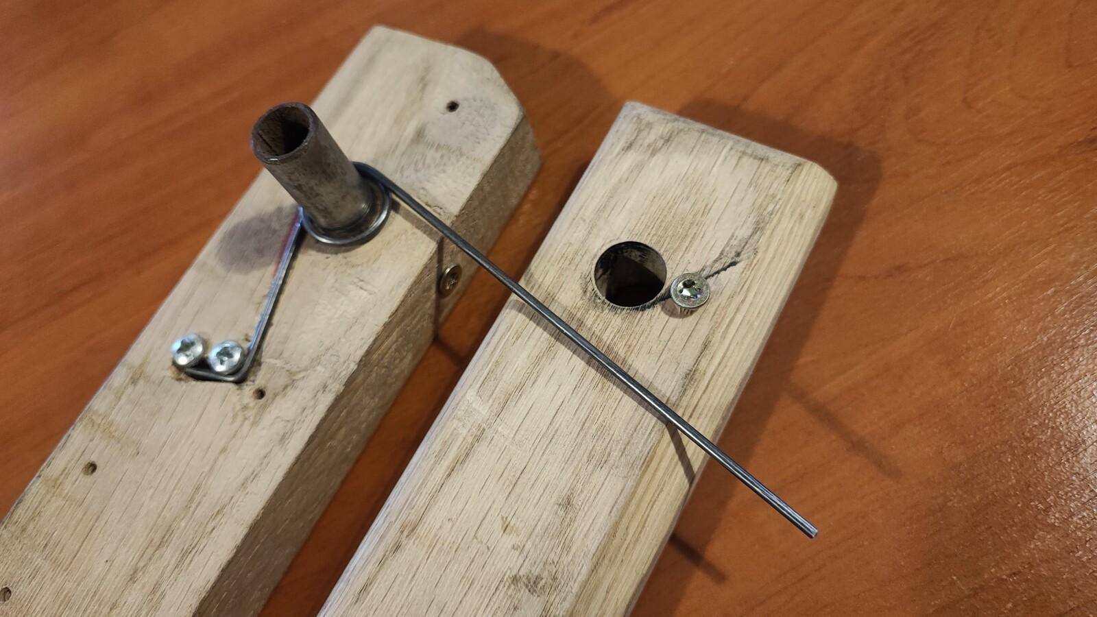
The spring bending tool was homemade - built from two pieces of hardwood, a steel pipe with a 14 mm outer diameter, and some screws. You might notice the red arrow on one side of the tool - that marks where I need to stop turning the wire to get the exact shape I want.
In the end, the springs turned out great!
MIDI Electronics
I ordered the electronic parts from https://www.midi-hardware.com
For a MIDI pedalboard, you only need two main components:
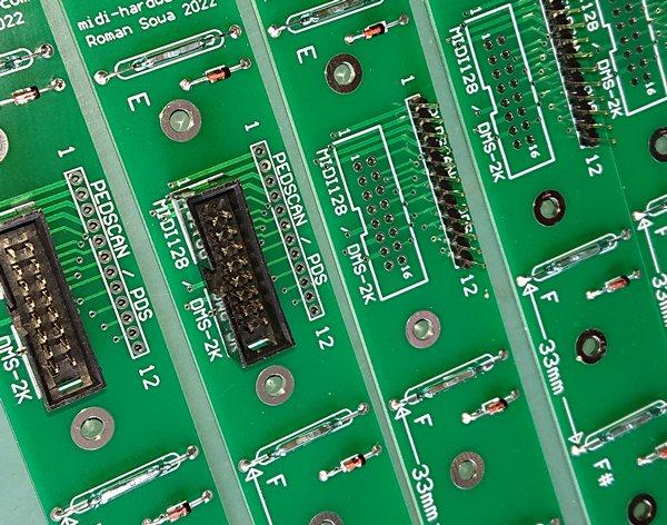
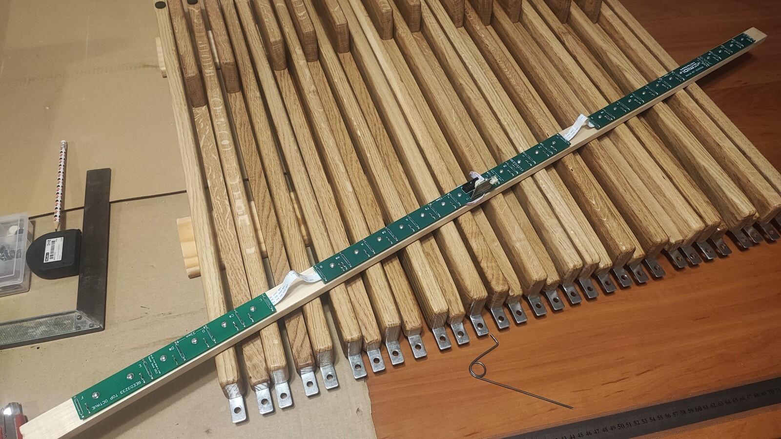
- REED32 module – three boards with reed relays (magnets are included)
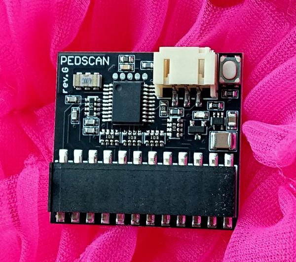
- PEDSCAN module – converts key presses into MIDI signals
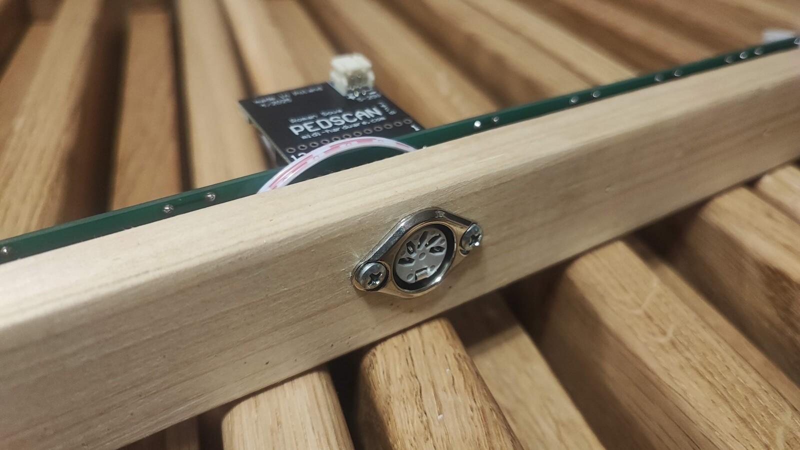
The PEDSCAN module comes with a short wire and a 5-pin female MIDI connector. I also ordered a battery holder (4 × AAA) and a few extra reed relays to keep as spare parts.
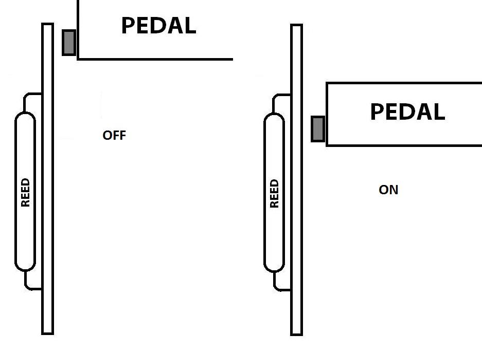
Short description of key activation system: REED32 module uses Reed relays. They are small, sealed switches that are activated by a magnetic field. Inside the glass capsule are two thin metal reeds. When a magnet comes close, the reeds are pulled together, closing the circuit - just like pressing a button. So, magnets are mounted on keys, and electronic board with reed relays is somewhere near (behind or below magnets). Activation distance from magnet to reed relay is about 15 - 18 mm.
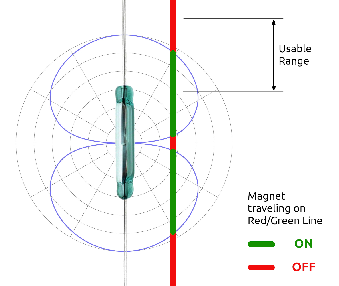
Fourth image in gallery below shows how reed relay behaves when magnet traveling in line parallel to it. In our case = Usable Range is actually key travel (16 mm), and we want note to be activated at half of that travel.
These modules are very reasonably priced, high quality, and professionally made. I have experience with electronics and prototyping PCBs, and I could technically build a REED32 module myself - but it would take a lot of time and wouldn’t be any cheaper.
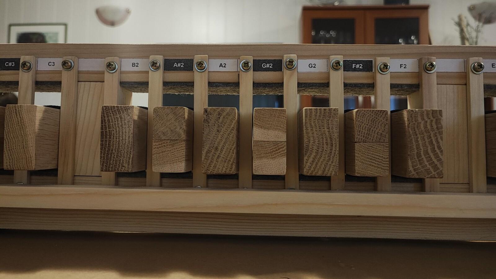
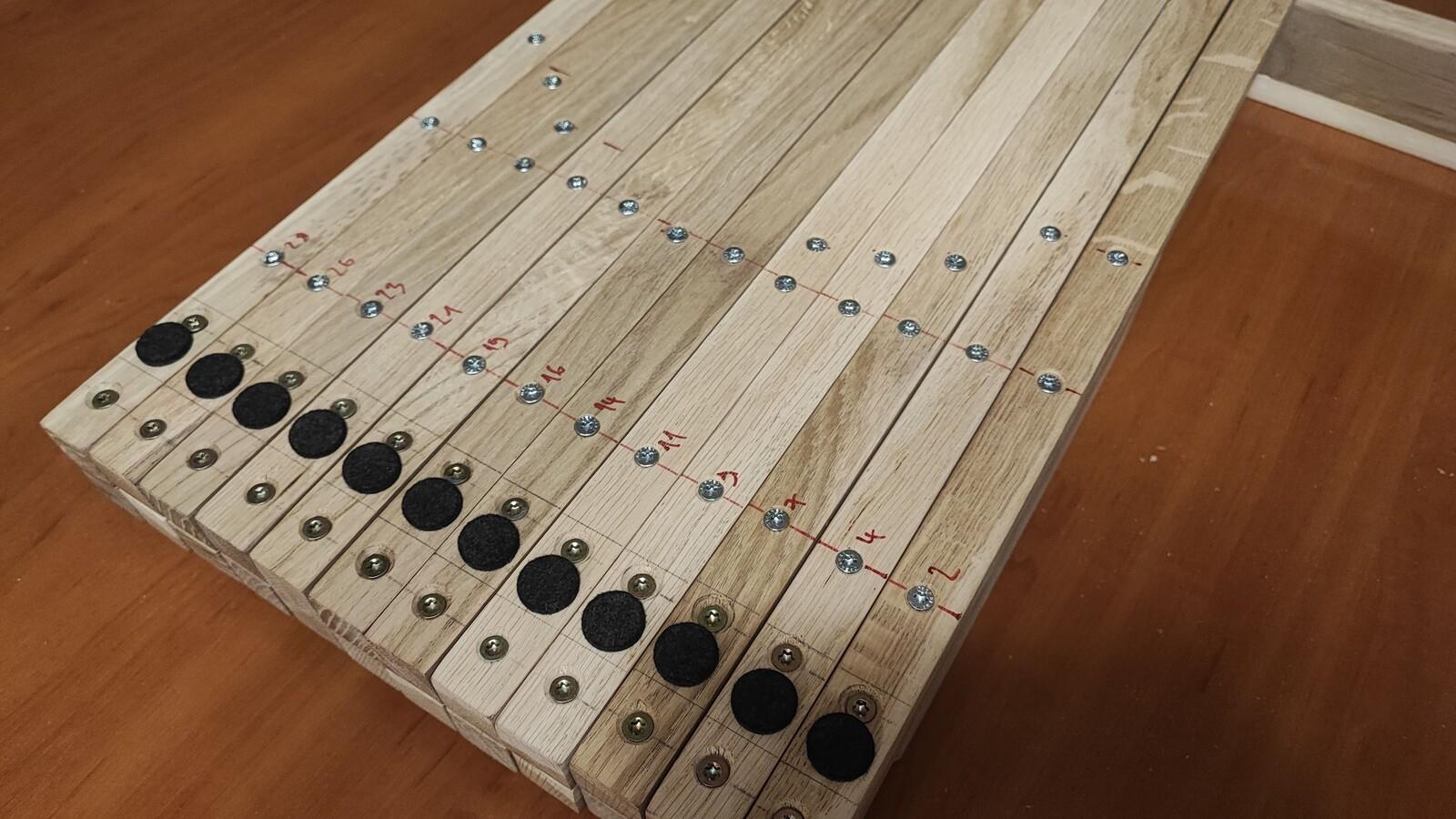
Note Activation & Mounting:
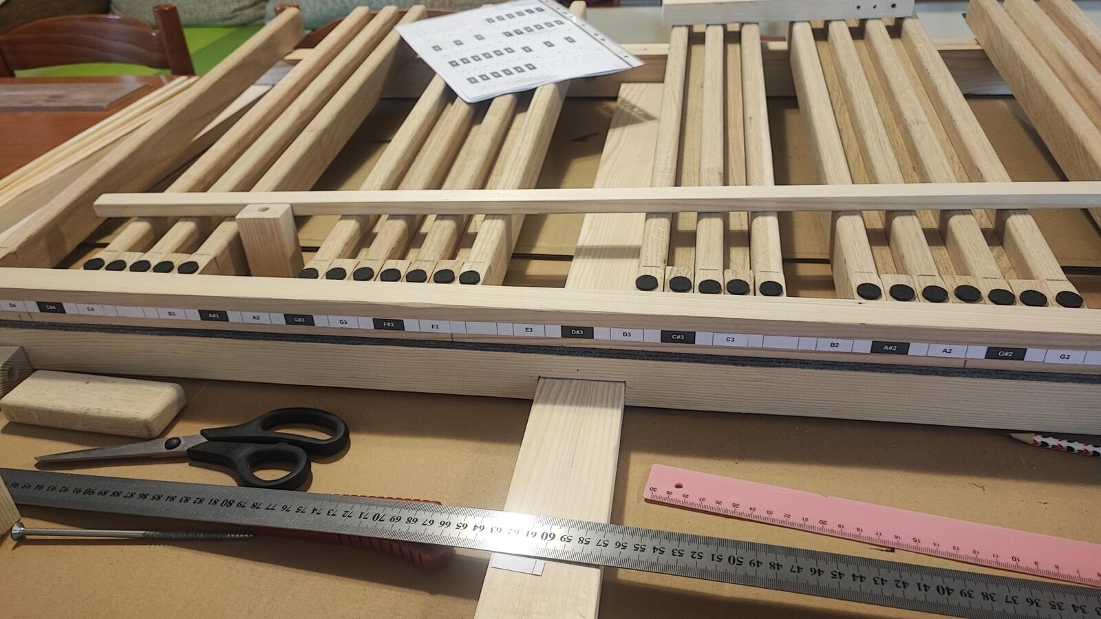
The notes are activated by magnets, which come included with the REED32 module.
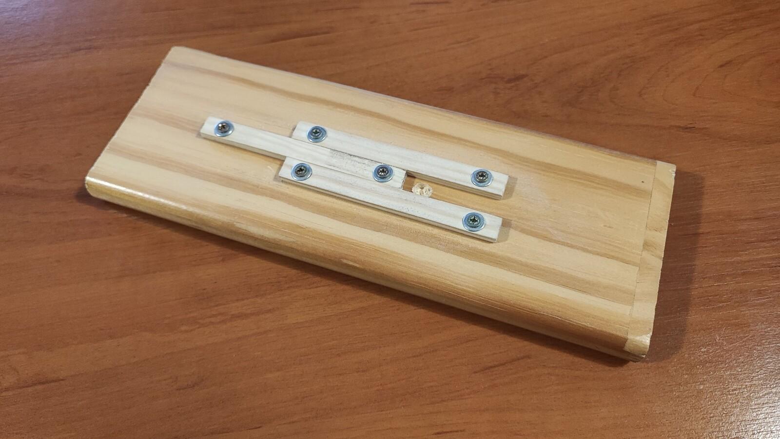
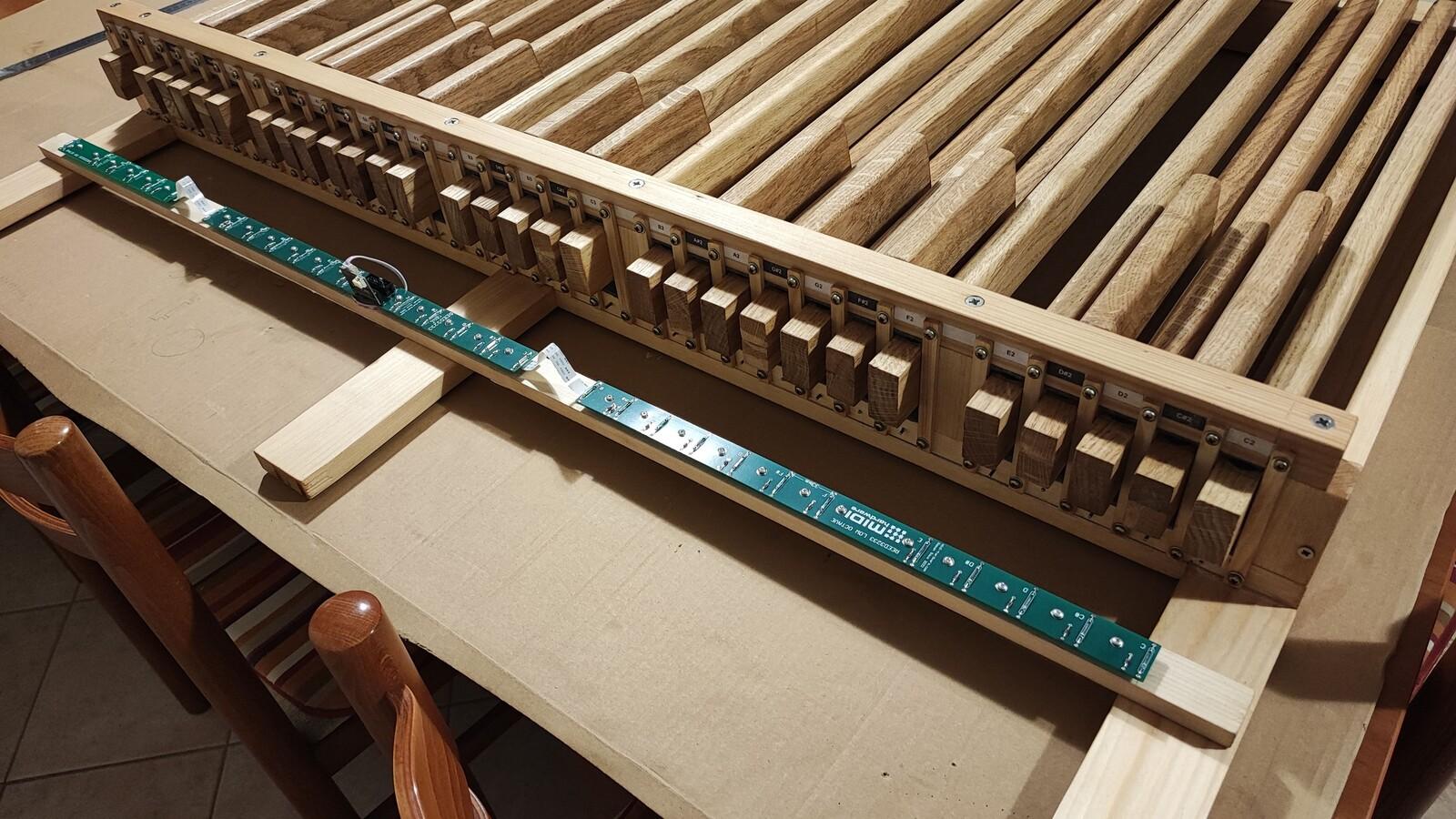
I mounted the REED32 boards on a pine wood element (15 × 30 mm) using metal 5 mm spacers (the kind used to mount motherboards in PC cases) and small pan-head wood screws.
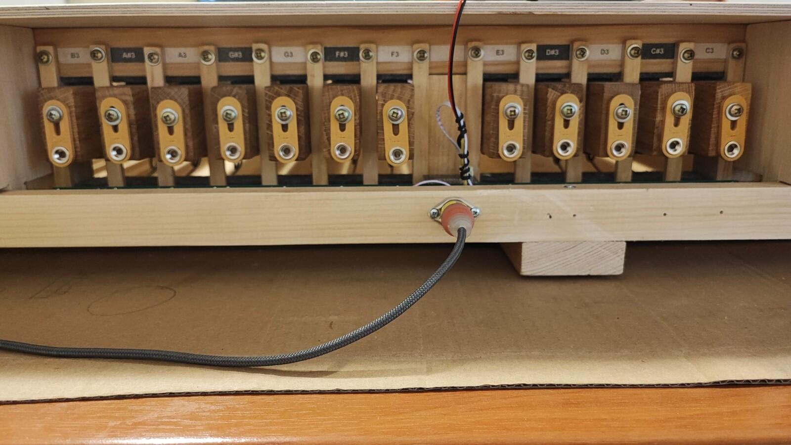
The MIDI connector is mounted on the back side of the same wooden element, behind the PEDSCAN module.
I chose to mount the PCBs vertically, with the reed relays facing the magnets.
Fine Adjustment:
I made a few small errors while cutting some of the key elements - something I only noticed after painting and oiling them. I didn’t want to sand and repaint again, but I was concerned that the distance between the magnets and the reed relays might vary, which could affect the height at which the note is activated.
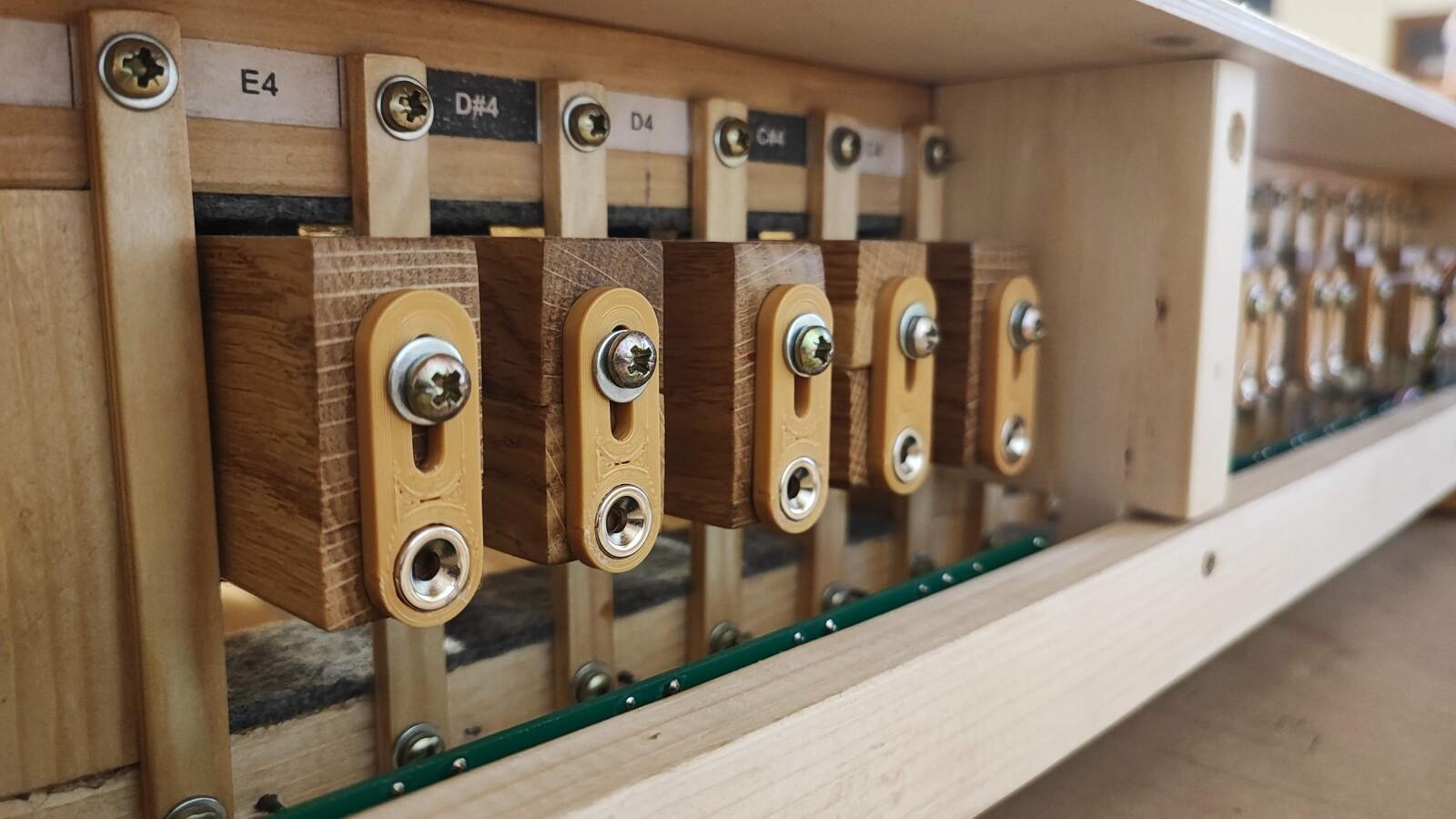
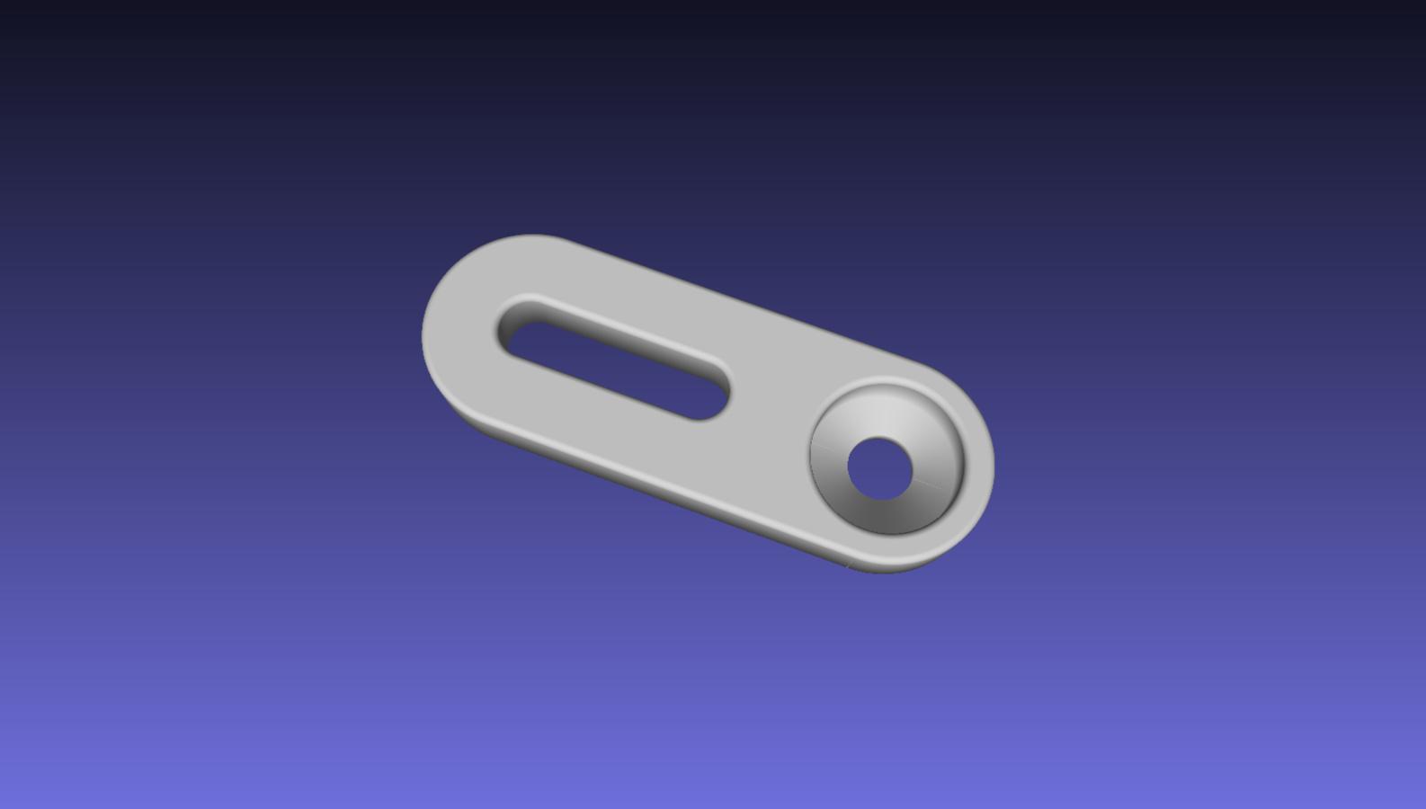
Roman from MIDI Hardware suggested placing each magnet by hand, adjusting it to the correct position, and then marking where to screw it onto the back of each key. Instead, I decided to make adjustment elements - very simple 3D-printed plastic parts that allow for vertical movement (±5 mm) of the magnets on the back of the keys. This allows for very precise and easy adjustment. The magnets are glued to these adjusters.
The best way to adjust a key: place something underneath the keys - in my case, it was a piece of hardwood, 8 mm thick. Press the key down to this position, and then slowly move the magnet down until you hear the sound. Tighten it in place, and repeat for all keys!
You can download STL file for 3D printer here: organ-adjuster.zip. It was made by my friend Dominik.
And as they say: a picture is worth a thousand words:
Mission Accomplished!
First Sound test:
I’m using GrandOrgue software (https://github.com/GrandOrgue/grandorgue) on my Linux laptop for the sound engine.
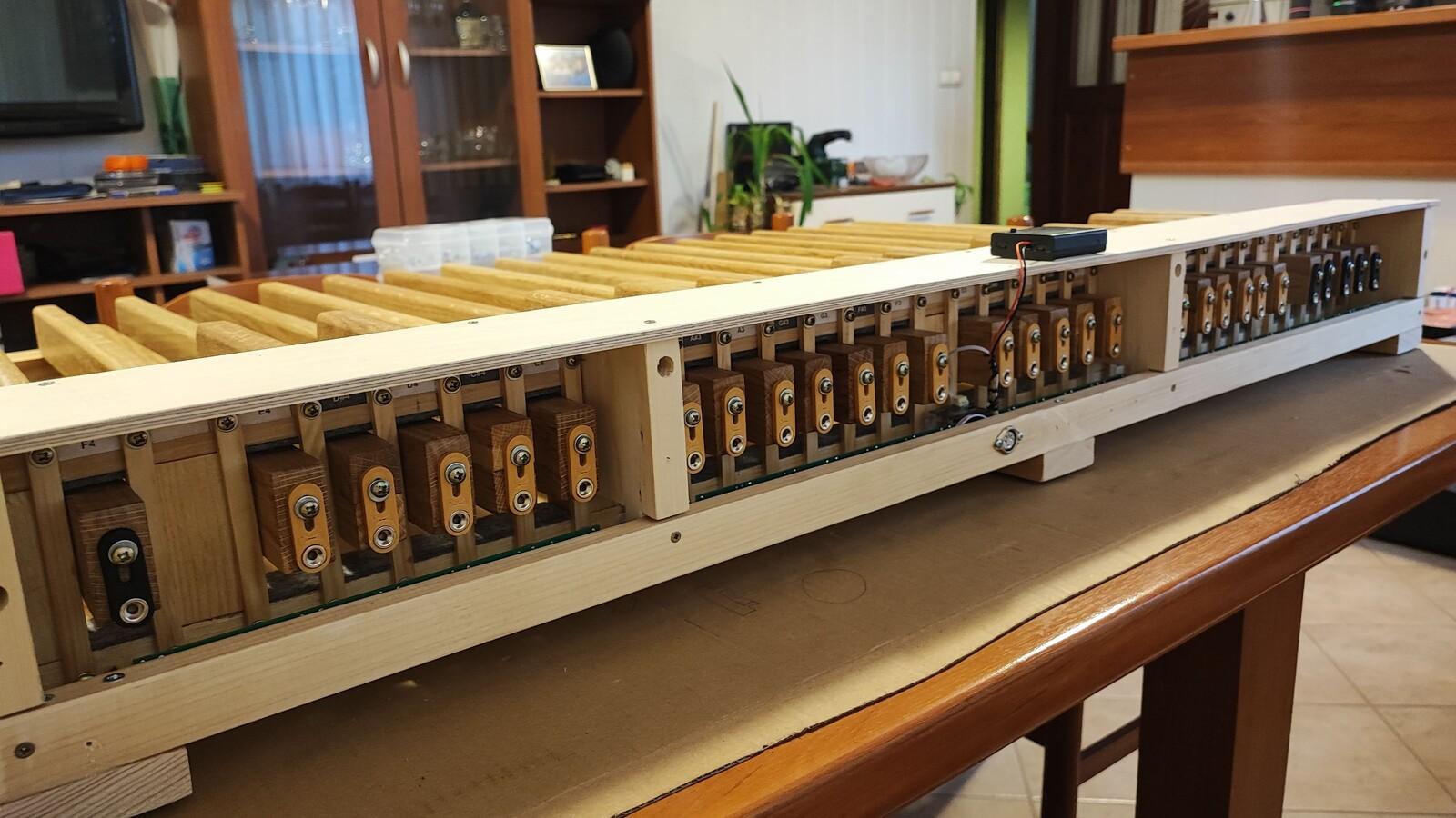
I also made a box (top and rear cover) around the electronic components to protect them from dust and mechanical damage. It’s made from 6 mm plywood.
The overall dimensions of the finished pedalboard are: 1224 × 820 × 150 mm.
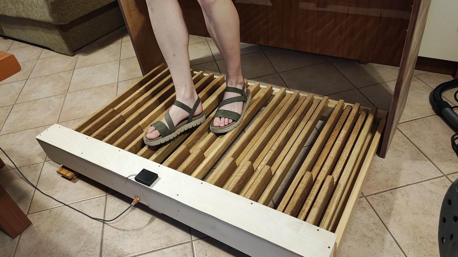
The keys move up and down smoothly, and it turns out that the cloth on the note space dividers wasn’t necessary after all.
I also did a quick build of a bench, using plywood from some old furniture - almost 70 years old! (One funny thing about the bench: I initially used a piece of plywood as a support between the legs - it was much easier for me than fitting a wooden bar. Then my son came along and revealed something I didn’t know: the bar actually has a purpose - it’s where the organist rests their feet when not playing the pedals! 😃 So, we added a proper bar later.)
This project took a lot of time, patience, and learning - but it was absolutely worth it. Building a MIDI organ pedalboard from scratch, with no prior experience in instrument making or woodworking, was a challenging yet rewarding experience. What made it even more special was doing it for my son, and seeing him use it to practice and enjoy music makes it all worthwhile.
While it’s not a beginner-level DIY project, it’s definitely something you can accomplish with basic tools, some research, and a bit of persistence. If you’re comfortable with electronics and enjoy working with your hands, I’d say - go for it!
If you have any questions about the build, need advice on a similar project, or want to share your own DIY instrument journey - I’d love to hear from you! Drop a comment below or reach out directly.
Also, if this post helped or inspired you, feel free to share it with others who might be interested.
Thanks for reading, and happy building! 🎶🔧
Monday, November 17, 2025 at 18:43:20
Impressive! Thank you for sharing